Showing posts with label serial. Show all posts

Thursday, January 23, 2014

Adding Analog Pins to Arduino pt.1

EDIT: I suggest reading this post instead:
http://jazz-disassemblies.blogspot.com/2014/04/adding-analog-pins-to-arduino-pt2.html
It is easier and more straightforward to program for.

All of the commonly used Arduino boards have Analog pins for use in converting analog data to digital data that can be manipulated via code. Arduino Pro Mini, Nano, Mega, Duemilanove, are all examples of boards that have 8 or more ADC pins and in some cases, they're not even all broken out!


In any case, 8 pins may not be enough for your needs, I know this fact first hand. The reasons why you may need so many ADC connections is not important, but figuring out a way around the problem is!

First, lets talk about know about the ADC pins before using them.
1. They may be used as Digital I/O.
2. They convert the analog voltages to digital data with a 10-bit resolution.
3. You don't want to waste them. ;)

The 10 bit resolution means that the data returned when using them as Analog inputs is within the range of 2^10, or 0 - 1023. I like to work with data in binary, but the data may be dealt with in decimal, binary or hex if you wish. Like:
B0000000000 - B1111111111
0x000 - 0x3FF
0 - 1023

Aside from the main point of this post, my needs are to use the values from potentiometers in an 8-bit resolution. I just found out that instead of shifting the data to the right twice (or divided by 2 twice) that the data range itself may be mapped to other values, both higher or lower. One way to read an analog input and mapping the value is as follows:


/*
Stupid simple code to read a pot value and map it to another range.
By Jazzmarazz

map(value, fromLow, fromHigh, toLow, toHigh)
*/

int A0pin = A0;

int potVal = 0;

void setup() {
pinMode(A0pin, INPUT);
Serial.begin(9600);
}
void loop() {
map(analogRead(A0pin), 0, 1023, 0, 255);
Serial.println(A0pin);
delay(500);
}

The map function could allow for you to map it to most any value:
map(analogRead(A0pin), 0, 1023, 0, 9);
map(analogRead(A0pin), 0, 1023, 0, 4095);
map(analogRead(A0pin), 0, 1023, 10, 100);
Whatever you like, for whatever purposes.

In addition, it is a good idea to read the constrain function:
http://arduino.cc/en/Reference/Constrain

Now to the point. To add many more ADC pins to the arduino, I suggest adding an external ADC via an SPI connection. Alternatively, you may use an I2C connection, but it seems like SPI devices come equipped with more analog channels. The MCP3008 for example, is an 8-channel, 10-bit ADC. This means that there are 8 analog inputs which all read back in the above mentioned 10-bit resolution.

To wire one such device to our Arduino, we must follow one of the Communication methods:
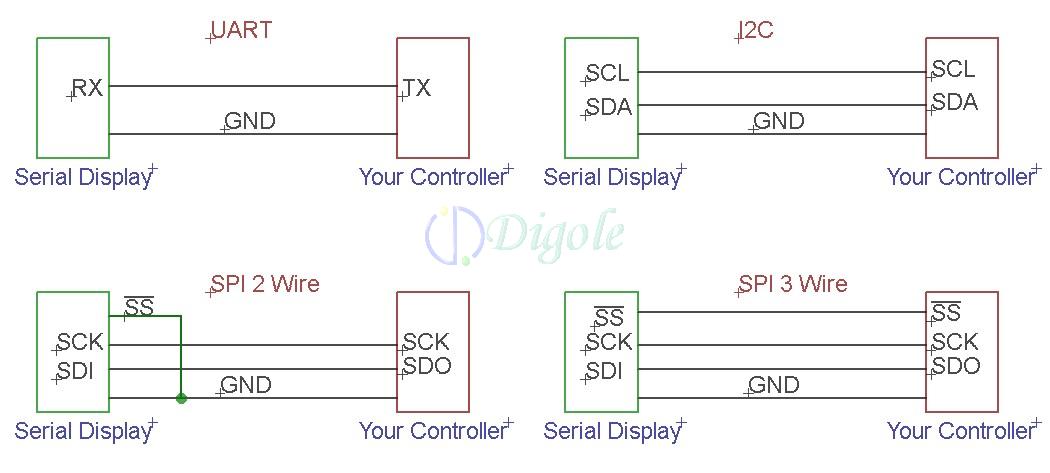
UART, I2C, SPI 2 wire, SPI 3 wire and lastly, 4 wire (full) SPI. An example of all four connections are shown below. In all of these cases, you need at least two things, a master device and a slave device. In our case, the master is our Arduino and the slave will be the MCP3008 ADC. Below also shows how you can daisy chain more slave devices to the same master bus. This is incredibly helpful because all of the devices are going to share up to three of the connections, and only have one connection that is unique to itself.


The shared connections are SCK, MOSI, and MISO while the unique connection is SS, but what do these connections mean?

MISO (Master In Slave Out) - The Slave line for sending data to the master,
MOSI (Master Out Slave In) - The Master line for sending data to the peripherals,
SCK (Serial Clock) - The clock pulses which synchronize data transmission generated by the master and one line specific for every device:
SS (Slave Select) - the pin on each device that the master can use to enable and disable specific devices.

Pretty simple, taken straight from the Arduino reference guide. You're probably wondering where the pins are. Now, you can write your own functions if you wanted to drop the external SPI slave anywhere, but a custom code is going to be much slower and it would be more easy to move your other connections somewhere else so that these pins are free for SPI:


Digital pin 13 is the Serial clock, 12 is Master Input, 11 is Master output and lastly, SS or Chip enable is 10, but I believe this can be moved where ever since it just requires a digitalWrite high or low. Low to enable of course.

That is about as complicated as it gets, honestly. Now, back to my needs. To iterate, I need to read the analog values of many potentiometers to assign to other devices, not on the SPI bus. We can do this two ways. Wire up all four connections, or wire up three connections and tie SS to ground on the slave only. If we keep SS connected to the Arduino, then we can expand the SPI bus to have more devices, more analog inputs, sensors, outputs, etc. IF we tie SS to ground, then the slave will always be active but can be the only SPI device on our bus.

Looking at the datasheet, there are two package types, the 3004 and the 3008. Both will take up all of the same connections, so lets focus on the 3008.


Pins 1 - 8 are the Analog input pins where we will connect the wiper of our pots. Pin 10 is the 1CS pin, which we will connect to !SS on the arduino. Pin 11 is the Din or Data input pin which will be connected to the Dout pin of the Arduino, MOSI. Pin 12 is the Dout which will be connected to the MISO pin. and lastly, the clock pin on 13 will be connected to Digital pin 13 on the Arduino.

Pins 16 and 15 will be bridged and connected to VCC or +5v. VDD is the supply and Vref is the reference voltage that the analog inputs are referencing. If we had a lower vref like 3v3, then our pots would have to be connected between Ground and 3v3, while the IC runs on +5v.

Pins 14 and 9 are the two grounds, Analog ground and digital ground, respectively. This may be one of the more confusing parts to hook up if you over think it. Copied stright from the datasheet:

"Utilizing the Digital and Analog Ground Pins The MCP3004/3008 devices provide both digital and analog ground connections to provide additional means of noise reduction. As is shown in Figure 6-5, the analog and digital circuitry is separated internal to the device. This reduces noise from the digital portion of the device being coupled into the analog portion of the device. The two grounds are connected internally through the substrate which has a resistance of 5 -10Ω. If no ground plane is utilized, both grounds must be connected to VSS on the board. If a ground plane is available, both digital and analog ground pins should be connected to the analog ground plane. If both an analog and a digital ground plane are available, both the digital and the analog ground pins should be connected to the analog ground plane. Following these steps will reduce the amount of digital noise from the rest of the board being coupled into the A/D converter."


What this basically means is that having analog ground and digital ground connected together may cause interference in the form of noise on the data traces. Since most of our Arduino board have only a single GND pin, we will have to take separating the two into our own hands. Some suggest dividing the two ground planes by a gap and then connecting them together via a small bridge like so:


They also suggest that you use separate power supplies. You should also remember to route any traces crossing the ground planes trough the bridge and not over the gaps. Being so strict will help you to reduce noise, but how much noise do you think that you actually have in your circuit? Are you running it on an unregulated series of AA batteries? A potato (joke)? Could you not afford filter capacitors? In most cases, the on board Arduino regulator is going to do its job in regulating the power supply, reducing noise and with capacitors between VCC and GND, yet more noise reduction.

Unless you plan on wiring up many different crystal oscillators, high speed devices, and wireless communications all on the same board, then your noise should not be readily noticeable.

Now enough of my tangents. I made up a quick MSpaint drawing of the connections:


That is the wiring diagram we will use, but for the time being, the MCP3008's are still in the mail. Once they arrive, I will write part 2 where we actually wire up the circuit and write some code to read from each pot. You may notice that the pinout is exactly 13 -> 13, 12 -> 12, 11 -> 11 and 10 -> 10. It would seem that the SPI functions were written to accommodate common SPI pinouts. You may see this on other SPI devices as well.

Thanks for reading!
Part 2: http://jazz-disassemblies.blogspot.com/2014/04/adding-analog-pins-to-arduino-pt2.html

Monday, October 28, 2013

Jazz Disassemblies Ep3: Sega Genesis Saving Teardown

I love the Sega Genesis, but rarely do anything with it. I have made a handful of reproduction carts in the past because there is nothing better than playing games on real hardware but I always have a regret after destroying a donor cartridge, whether it is sports or not. One of the goals I always set myself up with during a creating is to use 100% renewable components. By renewable, I mean of course modern and commercially produced components; nothing salvaged and nothing obsolete. Having nothing obsolete is very difficult in my circle of interests, but salvaging components is my greatest downfall.

During my journeys into the technologies that Sega and other companies used within the cartridges for the Sega Genesis/MegaDrive, I have found three official forms of saving data. Two forms use serial EEPROMs and the third uses the tried-and-true parallel SRAM with battery backup. My goal is to recreate these cartridges using new components and my stretch goal is to expand the addressable memory or just to improve them in some way while making the carts themselves renewable.

We already know that the plastic shells can be remade by the everyday hobbyist and their 3D printers and circuit boards can be fabricated by Chinese companies for pennies on the dollar. All that leave now is the components which are definitely on their way out of style. The components that we are looking for are 8- and 16-bit, parallel ROMs and RAMs. Referring to a statement above: by renewable I meant purchasable from Mouser or Digikey, etc in large quantities which will later be restored. Glancing at Mouser (My supplier of choice) I have already been able to locate a handful of ROMs and RAMs that come in both selectable 8- and 16-bit configurations!

The next goal I will have is to recreate the higher density logic with PLDs, but that is best left for another time.

1. KM62256 Parallel SRAM

These boards found in most of the miserable football and soccer games. Until I find another varient, I will cover one such board revision: "171-6279A"

The board seems to be made by Sega though I have long lost the ROM which was originally soldered in. It contains:

1x (CE) 47uF electrolytic capacitor
5x (C1-C5) .1uF ceramic capacitors
1x (BAT) CR2032 coin-cell battery
1x (IC1) 42-pin Mask ROM (27c160 equivalent) - 16Mbit
1x (IC2) KM62256BPL-7L, 32Kx8 bit (32Kbyte) Low Power CMOS Static RAM
1x (IC3) BA6162, Reset IC with battery backup function by Rohm
2x (IC4, IC5) 74HC00AP, Quad two-input NAND gate

I have already recreated everything on the board in Eagle PCB libraries including the board dimensions and general component layout. Tracing all of the connections is slower work and I will get to that eventually. In the meantime, my goal is to layout a functionally-identical board with 3v3 ROM/RAM, SMT caps and level shifters for proper data flow. THen we will have ourselves a flash cartridge!


Above you have seen the board itself with and without components. Ignore the text on the Mask ROM though since I just stuck a random IC in there to show it with one.

Looks pretty good if I do say so myself, though the traces are not as authentic as the layout. Sega never seemed to use top-side pads. They have vias which allow for double sided boards, but I have only seen EA cartridges that use top-side pads. These pads of course make for miserable desoldering since I need much more heat... and patience.

Some fun facts about this board is that the ROM is 16-bits but the SRAM is only 8-bit. Although I do not have the full details on how the software accesses these, the Gen/MD has two pins which are called !LDSW and !UDSW (Upper Data Set Write and Lower Data Set Write). When reading from RAM, the processor ignores the upper byte of data since there should be nothing there. While writing though, the !LDSW pin goes low which enables the !WE pin on our RAM. These two pins are for transferring 8-bits (one byte) at a time rather than 16 (two bytes).Not knowing how to activate either of these pins, it would seem that someone may add a second SRAM and use the currently unused !UDSW pin as the enable.


The above picture is how I found the glue logic for addressing our memories. Only 6 out of 8 gates are used which is a waste of space and battery power since the unused pins are connected to the Vout pin on our reset IC. If you think about it, the three NAND gates that have both inputs connected act as NOT gates which is something we would take into consideration if we were to redesign this with single-gate SMT ICs or on a PLD.

one problem I have with this board is that A21 and A22 are simply left hanging. Just a guess, but using A20 as a ROm address and A21 in the logic would expand the addressable memory, but Sega chose not to for some reason.

2. Acclaim Serial 24LC02B RAM

The next board I will cover is the P/N 670120 REV 2 by Acclaim. The contents of our board are as follow:

1x (C1) 47uF electrolytic capacitor
4x (C2-C5) 0.1uF ceramic capacitors
2x (R1, R2) 4.7K Ohm resistors
1x (U1) Mask ROM (capacity not yet known)
1x (U2) 74ALS138N, 1-of-8 decoder/demultiplexer
1x (U3) 74ALS74AN, Dual D-type flip-flop with set and reset
1x (U4) 74ALS125AN, Quad TRI-STATE Buffer
1x (U5) 24LC02B, I2C™ Serial EEPROM (2K capacity)

As you can see, the naming routines is different than that of Sega and yet again, we could reduce the chip count to much less with a PLD. U2-U4 could easily be designed in a PLD to reduce space and cost. For the time being, I assume the resistors are pull-ups or pull-downs.


3. Acclaim Serial 24LC04B RAM w/ LZ95A53

You're probably thinking that I recycled this board from a previous post and yes, yes I have. It does pertain to the topic though and I can probably shed a little more light on the special IC now that I know more about !LDSW and serial eeproms.

Anyhow, this board contains:

1x (C1) 47uF electrolytic capacitor
4x (C2-C5) 0.1uF ceramic capacitors
1x (R1) 10K Ohm resistor
2x (U1, U2) Mask ROMs (27c160 equivalents)
1x (U3) Acclaim LZ95A53 (memory mapper, glue logic, serial data interpreter, etc)
1x (U4) 24LC04B, I2C™ Serial EEPROM (4K capacity)


Above is the board that I created by probing all of the traces. Looks nice, but my next goal would be to reverse engineer the Acclaim's LZ95A53. Unfortunately, I have no scope to do so...


The above picture is my schematic which shows the connections on the LZ95A53. I had to make an addition to my cartridge connector since it uses several different pins that very few others use. I believe that the Acclaim's LZ95A53 IC contains the same logic as the board which used the 24lc02 serial RAM. Again, I cannot test this theory.


In hindsight, all of these boards used 27c160 equivalent Mask ROMs. The 27c160 can store a 2MB ROM which means the board with 2 Mask ROMs had a 4MB game. A piece of information for those making reproduction carts with the 27c400, 800, 160 and 322's, the first three mentioned all have a !BYTE pin. This pin allows for the EPROM to function as either an 8-bit or 16-bit ROM which means you may use it in many different systems.

Besides a little bit of work on the silkscreens, these boards are all ready to send to any fab house, granted they make 1.6mm thick boards. I will also be adding some more pictures of the other two boards shortly. Thanks for reading.

Sunday, September 22, 2013

Populating the GB-Programmer (Jazz-Assembly #1)

The board has been designed to accommodate different methods of programming the Atmega8515 (hereby simply called 8515). Once programmed, you may never choose to reprogram it again because there may never be updates to the firmware anytime in the future.

Step 0.
Admire your beautiful new toy. 

It shall prove to be very useful regardless of your individual purposes. Also, at no time should you power your board until I say so.

Step 1.
Soldering both SMT ICs

The picture below is of two board prior to me cutting them apart. To reduce cost, I panelized my design.


Image Hosted by ImageShack.us

You may choose to solder one IC at a time or both at once depending on your skill and resources. It would be highly suggested to use either a hot air gun or some type of oven and solder paste. Soldering by iron is perfectly possible, but creates more chance for failure. If you are a frequent reader, you should know that I now own an awesome hot air station, so I also bought a tube of solder paste.

Simply apply a very small amount of solder paste to the bare pads and carefully place your IC over top of them. Make sure that it is aligned as closely as possible, not forgetting to orient pin 1 in the right direction. Pin 1 is designated by the white circle on the board.

Image Hosted by ImageShack.us

Image Hosted by ImageShack.us

Once you finish both ICs, make sure that there are no shorts in places that they may not be. If you find one, attempt to draw the solder off of the pins with your iron or solder wick. Check it again and once satisfied, move on.

Step 2.
Through-hole components.

As much as I had hoped not to use any through-hole components, my audience insisted. The through-hole components required include:

2x 0.1uF ceramic capacitors (may be labelled 104)
1x 4.7uF electrolytic capacitor
1x 10K ohm resistor
1x 1K ohm resistor
2x 220 ohm resistors
2x LEDs (two colors)
1x female USB type B connector
1x gameboy cartridge connector

For the time being, do not populate C4, R6 and R7. These are not relevant at this time. You may choose to use a 6MHz ceramic oscillator, but I suggest saving the money and moving on. If you do though, cut the trace leading from it to the FDTI chip.

Start by placing the leads into the holes and bending them away from center so that they stay in place. Sodler each component on the underside and clip the legs at the board. Some people would suggest to clip them before soldering though.

Also make sure that the electrolytic capacitor (C3) faces negative lead down as shown below. Each components has the appropriate value marked on the board, so you cannot go wrong. Seating the gameboy cartridge connector may be the most difficult through-hole component. It has the most pins and each of these pins could be slightly bent from originally removing it. Take your time and do not stress.

Image Hosted by ImageShack.us

The LEDs can be any color you like, but know that the one farthest from the resistor is power and the other one is activity. I prefer my toys to have a green power LEd. ;)

Image Hosted by ImageShack.us


Step 3. 
PC Connection

Check your SMT soldering ONE MORE TIME. If and only if there are no shorts between pins, connect the board to your PC and cross your fingers... IF all is well, the LED should light up and a driver should automatically install for your device. It will also be given a COM port number.


Image Hosted by ImageShack.us

Step 4.
Programming the FT232RL and 8515

Thats right, you're going to program both ICs. There is only one modification that needs to be made to the FT232RL (hereby simply called 232) which is to make it output a 6 MHz clock rate. This is for the 8515 to run on.

First, the 232's internal eeprom must be modified. To do this, we will use FT_Prog found on the FTDI website here:
http://www.ftdichip.com/Support/Utilities.htm#FT_Prog

Only one modification must be made and that is to change the CBUS0 pin to act as a 6 MHz clock. We will not worry about the other pins because they are all unconnected. CBUS0 is one of five programmable I/O pins and there are many options to choose from, but I am not going to cover these here.

Install FT_Prog and run it. You'll be greeted by a well designed GUI ... just don't touch anything. plug in your device and it should install a driver if it has not already. Once "Your device is ready to use" go ahead and click "Scan and Parse" which looks like a magnifying glass. Your device should pop up in the dialog box under device tree like this:

Image Hosted by ImageShack.us

You can see that your device is already programmed, but we must now change one function. Expand the device tree as such:
FT EEPROM -> Device Specific -> IO Controls -> C0
Use the drop-down to select CLK6 in the C0 bus only. The other pins are all useless as they are not connected to anything. Ignore them.

Image Hosted by ImageShack.us

Click on the lightning bolt which is the program button, make sure your device is selected and press "program" if and only if you are positive you did not change any other settings.
The bottom of the window will say finished and then ready. Close the window and close FT_Prog, then disconnect your programmer.

Image Hosted by ImageShack.us

Reconnect your device once more and it should install the drivers again and give it a new COM port. You can now move on, but if you were to open your device in FT_Prog again, you would notice that C0 is still set to CLK6. Good job!

Just a note, but the reason you should not touch any other options in the eeprom settings is because there are too many settings that can be set incorrectly. For example, if you were to program your device to use an external oscillator, it would be rendered useless and you spent a lot of time and energy soldering that chip perfectly! So be careful!

Step 5.
Programming the 8515.

The easiest way to program the 8515 is via FTDI BitBang. It is a totally new concept to me, but incredibly useful considering how much people want to charge for ordinary ICSP programming kits. It may be a tad bit slower at programming, but since you will only program the 8515 once, it does not matter.

I put together a file-pack to get you started. This pack  includes AVR_DUDE, my custom config file special for this programmer and the hex file which needs programmed to your 8515. I am writing the guide on the GUI version of AVR-DUDE. Everything is easier with a GUI, though you have to show a little love for the tried and true command prompt. ;)

Download it here:
http://www.noisechannel.org/wp-content/uploads/2013/09/GB-Progger-kit.zip

Lets get started.

Go ahead and hook up your programmer if it is not already. Open avrdude-GUI.exe.
1. Direct the first box to your avrdude.exe
In our case, we will be using the avrdude-serjtag that you downloaded.
2. Pull down the "Programmer" Box and select the "FT232R Synchronous BitBang for Jazz (GBProgger)."
3. Leave the port drop box blank.
4. Locate "ATmega8515 (m8515)" under the "Device" drop-down.
5. Type "-P ft0 -B 4800" in the "Command line Option" box. It should look just like this below:


Image Hosted by ImageShack.us

6. Click the "Read" button under Fuse. This will show you the fuse bits on your 8515 which must be changed. It does not matter what they are now.


Image Hosted by ImageShack.us

7. Change the fuse bits to C910 as pictured and hit write. It will be very fast and just ask you if it went well.


Image Hosted by ImageShack.us

8. Now erase "-B 4800" from the "Command line Option" and browse for the hex file under Flash then hit write. It is also fast, too fast for me to get a screenshot even.


Image Hosted by ImageShack.us

9. Exit and done. Disconnect your device and reconnect it. If all went as planned, you now own a GB Programmer and Dumper for whatever needs you may have.

Lets test it out, shall we? That is another blog post, for another time. See you then! :D

 Cheers,
Jazz

Acclaim Custom IC - Sega Genesis/MegaDrive

While viewing different game cartridge boards for the Sega Genesis, I came across a few Acclaim boards. I no longer can remember what games they were because I have long removed the Mask ROMs, but one board has three 74-series ICs and a 2k eeprom for saving purposes. The fact that they utilize both parallel and serial communication methods causes problems for me, but we will get to that later on. In any case, the second board contains the 20-pin "Acclaim LZ95A53" IC (datecode 9453 A). this board also contains a 24lc04, which is double the size of the 24lc02 on the other board.

While searching the custom chip, I found that there is little information on it. I can only come to the conclusion that it is a custom memory mapper AND parallel to serial data conversion IC.

The three ICs on the first board from Acclaim are the 74ALS138 decoder used on many many other boards for memory expansion, a 74ALS74 Dual D-type flip flop and a 74ALS125: Quad bus buffer with three states. I cannot prove this theory yet, but I believe the Acclaim LZ95A53 is all three of these ICs built into one. 20 pins could easily achieve this since many pins are shared and many others are not used at all on the other chips.

Here is the first circuit board with all four ICs. Four ceramic capacitors, one electrolytic and two resistors. The board originally had only one mask ROM so I assume it was a game of 2MBytes.

Image Hosted by ImageShack.us

Image Hosted by ImageShack.us

And here is the circuit board with only two ICs. The custom "Acclaim LZ95A53" can be seen at the top right. By reducing the three chips into one, they also reduced the required space on the board, reduced component count and most likely cost. They also switched from their own board to a board made by Liteon. There are several improvements that I can see on the board when they made the switch. Not only is the copper much more smooth but the solder mask is shiner and they even tented the vias. I rarely see tented vias on game boards. The drills are also smaller and less sharp. The previous board has splintering around all of the drills.

Image Hosted by ImageShack.us

Image Hosted by ImageShack.us

Looking at the revision designators on the boards, the liteon is newer. One more thing that I noticed about both boards is that neither have break marks to show that they were panelized. Acclaim chose to finish off the sides very nicely which is odd. Game boards were technically not supposed to be seen by the end user, but they took the extra time and effort to clean them up as opposed to (looks over at other boards on desk) konami and Capcom. A third Acclaim board that I own which is yet older than the two in detail above has also been finished on all four sides.

In conclusion, Acclaim seemed to have cared a little more about the games that they produced. Going the extra mile to make their boards of higher quality and to develop proprietary ICs. I can respect them for this though I never had any doubt about them. EA on the other hand...made boards that I despise. I may post about them another time. For now I will be following the pins on the LZ95A53 back to their origins and proving whether or not it is simply a combination of three 74-series ICs. Granted it is, I will have a pinout shortly there after.

EDIT:

I have since begun following pins on the board from the custom chip to other locations. So far it would seem that I was correct, mostly. The chip is definitely decoding ROM address and possibly RAM addresses (granted your board requires parallel RAM) and has connections with the Serial RAM; however, it is also making connections to the !AS pin on the 68000 and the !LDSW and !UDSW pins. these pins are beyond me, but I have read they have to do with writing only a single byte at once rather than the full 2-bytes (16-bits) that it capable of.

I will continue to edit the diagram below once I have more information:


          __  __                  
A20    1=|      |=20   VCC     
A21    2=|      |=19   NC 
/C_OE  3=|      |=18   !OE2(ROM2)     
/C_CE  4=|      |=17   !OE1(ROM1)     
/AS    5=|      |=16   NC
D0     6=|      |=15   NC     
/RES   7=|      |=14   NC     
/LDSW  8=|      |=13   NC
/UDSW  9=|      |=12   SDA(24lc04)
GND   10=|      |=11   SCL(24lc04)
         |______|

Also note that pin 12 which connects to SDA of the serial eeprom is also connected to VCC via a 10K ohm resistor. I assume this is a pull-up resistor for data  

Saturday, July 27, 2013

Pre-Blog Projects Revisted pt. 1

I was digging through old photos on my ImageShack profile and decided to talk about them. There is no particular order, but each has a story to go along with it.

Shown below is from when I was working with the z80 (as if I ever stopped). I pulled this z80 from a dead Sega Genesis and built it onto a breadboard to test the functionality. It turns out whatever was wrong with the Genesis was not the z80. The testing circuit was simpl; executing NOPs (no Operations) by connecting all Data pins to ground via a pull resistor. This caused the Address pins to run from $0000 to $FFFF bit by bit and since each Address pin was connected to an LED, the LEDs would light up (very quickly mind you) as a binary counter. The only LEDs I couls see flashing were the high erbits becuase the lower bits were mush too fast.

Also shown is a memory chip which remained unattached, an AY-3-8910A Programmable Sound Generator IC, a CTS256A-AL2 Text-To-Speech Controller IC which has gone unused because I do not have the SPO256-AL2 companion voice synth IC. And lastly, in the bottom corner is just a simple xtal running through NAND gates to clean up the signal.


Here is one of my favorite projects! This was a simple Atmega microcontroller based logic Analyzer which I redesigned around very strict limitations. Original credit to:
http://www.serasidis.gr/circuits/mini_logic_analyzer/miniLogicAnalyzer.htm
The limitations were that I wanted it to fit inside of a nintendo gameboy, run on 4x AA batteries like the gameboy and use the battery contacts, battery compartment, power switch and screen location from the gameboy itself.

First came the board. The gameboy has a rather small square mainboard which has several specific mounting holes. All measurements were done very crudely with a clear mm ruler...I sure wish I had a digital caliper. Luckily, everything fit (the second time). The board shown is the board that I printed myself with the transfer method as it is called. you may print your circuit onto a clear coated paper (I use magazine pages) and then iron the image onto a copper clad board, clean and immerse into an etchant solution. Maybe I will write up a tutorial at some point, but it is pretty straight forward. Since this was not my first board to have etched myself, it turned out wonderfully. Some boards...did not. But alas; I am persevering!Notice my old logo etched on the right. ;)

Image Hosted by ImageShack.us

Here is the same board after being populated by hand and placed into the gameboy. "BA-DING" ... just kidding. At least the LED shows power is applied. The microcontroller is on the underside since I designed it to fit into a socket. Another restriction that I just remembered was that I wanted to use the gameboy's buttons to navigate through the program. The bottom of the board is suppose to hold ordinary push buttons, but I did not fit them so that I could wire up the GB's.

Image Hosted by ImageShack.us

LOOK IT WOR......thanks China for the crappy LCD screen. >_>
Yes, the text is indeed upside-down, but at least I managed to get it working. This happens to be the second problem with this particular LCD. The first was that it runs on 5v, not 3.3 like the datasheet stated. Also, the control pins were all sorts of switched around. With a little retrcing of my board design, I had that sorted out as well. My favorite problem (sarcasm) was that the LED backlight happened to be high-enabled rather than low...so if I had not caught that as soon as I did, they probably would have been damaged.

Image Hosted by ImageShack.us

Add the case and logic probes (minus one)...and...Ta-da! A working logic Analyzer!

Image Hosted by ImageShack.us

The above mishap from China isn't true for all electronics though. The USB ISCP below works very well. The only problem is that the ZIF socket is hardly ever used. It is used for a few Serial programmable microcontrollers and eproms. The only eproms I use are parallel programmable for which I use a different programmer.

On either side of the programmer are my sockets to program the microcontrollers (written on the sides of the boards). YES, I realize that having these boards entirely kills the 'S' in ISCP, but few of my designs fit an ISCP connector...

Image Hosted by ImageShack.us

Here is a smaller project: two guitar pedal boards. These board were suppose to use the PT2399 IC to create a variable echo effect, but I never found all of the needed components so the board were stores away in one of my many crap-boxes.

Each board controls an analog mono audio signal and connectos two potentiometers for control. on the right of the board is where a 7805 voltage regulator would fit and at the center is where the chip would have been socketed. Again, I degin all of my boards using Eagle CAD and then print them onto a PDF so that the vectorized image remains thew highest quality and static size.

Image Hosted by ImageShack.us

This is a print of a gameboy cartidge programmer designed my Reiner Zeigler to be used with modified cartridges or other commercial carts. It allows for you to read and write not only ROMs, but also RAM data if present. This board is the reason why I built the Atmega 8515 programmer above.

Reiner designed two version of the board; one for USB and one for Serial. I tried my hand at the USB because at the time, I didn't have a serial connector on the desktop I built...as is one of the few disappointing facts about new computers.

Image Hosted by ImageShack.us

lastly is the board after etching. It turned out terribly! This was the first board I had ever etched so I can't really complain. It was a learning experience and nothing more. Since nearly all of the data and addressing pins bled together, the board was tossed and I tried again later on after redesigning the board to accommodate my barbaric etching methods. I think the problem was that I didn't iron it long enough and with enough pressure. Some of the plastic ink peeled off or bled together.

Image Hosted by ImageShack.us


Tuesday, July 2, 2013

Update: Jul-2-13

Since my last post, I have not only acquired an Apple IIe but have set myself on a journey of self-betterment and creation. (Im gonna build something)


Image Hosted by ImageShack.us

Clearly my Apple is beaten up with keys missing and ... a makeshift floppy drive but it is one of the coolest things I have ever owned. The internals are simple enough to follow myself and the features are incredible. For the longest time I had been planning a new device to engineer and produce, but if it wasn't for the Apple II, I may still be at square one.

To begin with, the uP inside is the 6502. Quite powerful for its time and variants are still being produced today! For the device I am designing, I have chosen the 65c816 which is a higher processing faster uP than the 6502. It still keeps a certain amount of backwards compatibility too which may or may not come into play with my computer.

I am now studying the 65c816, latching process, addressing methods, etc. The thing can address up to 16Mbytes which is absolutely astounding! I have started looking into I/O options such as the DUART which I may use for MIDI and controlling an LCD module for serial output. This lead me to find the TellyMate which converts serial data to composite video. The TellyMate is in such a small package, that I have decided to fit one into the shell so that it can be put onto a television.

As for the main purpose, I am designing a computer to cater to the chiptune artist. There will be at least two synth chips (vintage of course) and an expansion port for other software. The expansion port I have decided will be not only used for software, but for addressing custom hardware devices designed by other people in the future. Gotta love them modders. I may design a docking system to connect a control board with buttons, pots and other components to control filtering, looping, controlled interference and other attributes of individual sound channels.

If you're a fan of LSDj and the DMG-01, then you may want to follow my blog. I will be starting a kickstarter eventually which will have all of the information and replace the gameboy entirely. My handheld computer will not only have more sound channels, but built-in midi control and the main focus is the modder. I will create the very most mod able toy ever.