Tuesday, February 11, 2014

NES TSOP ROM Adapter Development Board

The title is quite a mouth full, but I have been working on an adapter board for use in the NES. While EPROMs are still available for burning ROMs, (for development purposes of course) they are running out.

27C, 29F, 49F series chips, etc. They are no longer produced and as stocks dwindle, prices increase. Some companies do still make ROM chips though! The newly produced chip are rarely made in a DIL package though, so an adapter is needed, else the user very carefully hand solders each pin. Even with each pin hand soldered, how are you supposed to program the ROM to it? With an adapter, thats how.

So say you have an adapter for one such new ROM chip. Is the final pinout the same as a CHR mask ROM, PRG mask ROM or the old 27Cxxx/29Fxxx/49Fxxx pinout? How about all three? The thing that my adapter board has, which others may not, is solder-pad jumpers to change the pinout of the two rows of pins. Each pad is named so the user can see which pads to use when they want the pinout of a CHR ROM, PRG ROM or normal flash ROM.

The only draw back is that the Chip that I used, the GLS29EE010, is only a 1 MegaBit EEPROM. That is only 128 KiloBytes. Many NES ROMs are small enough to use these, but many complex RPG's are much larger. Now for a beginner NES programmer, 128KB is plenty of room.

Anyhow, the biggest reason that I wanted to make this adapter is so I can configure the board to be a 29F010, program it with my Willem Programmer and then reconfigure the pads for either a CHR ROM or a PRG ROM. This makes it so I do not have to modify the traces on an NES cart or connect wires all over the board.

In the pictures, you can see how far I have come. I still need to place the solder pads in convenient locations and the last thing I will do is make the board smaller. As you can see, the board protrudes past the through-hole pins. This small amount of extra board may not cause any problems, but it is best to be safe.

TOP:


BOTTOM:


SCHEMATIC:


UPDATE:


The above pictures are of my finished board. The top side contains the filter capacitor, a pull up resistor for the Write enable pin and the 128 KByte ROM itself.

The bottom side has all of the jumpers which are labelled accordingly. If you want the pinout of a CHR ROM, solder the jumpers which are labelled CHR, but if you want to program the chip with your EPROM burner with factory settings, the solder the 010 jumpers and set your programmer in software as a 29F010. Its as easy as that!

I have also reduced the size to 41.91mm x 19.05mm. The filter capacitor is optional since the standard cart will have one immediately next to the power pin of the original mask ROM. The pull up resistor is required unfortunately. Many IC's now-a-days have internal pull-up or down resistors so that pins can be left open or hanging, but the datasheet does not say anything about pull up resistors and this is not a pin we can leave to self-oscillate!

Thursday, February 6, 2014

The Nintedno Gameboy Pocket's CPU pinout

I finally got around to probing the pins on the gameboy pocket's CPU and made a diagram. The CPU is not the same as the CPU inside of the original gameboy or the super gameboy SNES cartridge. When I get the chance, I will draw a schematic of the entire gameboy pocket.

Pinout photo direct link (huge): http://imageshack.com/a/img835/3936/nyix.png

  1.  A0
  2.  A1
  3.  A2
  4.  A3
  5.  A4
  6.  A5
  7.  A6
  8.  A7
  9.  A8
  10.  A9
  11.  A10
  12.  A11
  13.  A12
  14.  A13
  15.  A14
  16.  A15
  17.  D0
  18.  D1
  19.  D2
  20.  D3
  21.  D4
  22.  D5
  23.  D6
  24.  D7
  25.  /RES
  26.  VIN
  27.  SO1
  28.  SO2
  29.  MD7
  30.  MD6
  31.  MD5
  32.  GND
  33.  MD4
  34.  MD3
  35.  MD2
  36.  MD1
  37.  MD0
  38.  SOUT
  39.  SCK
  40.  SIN
  41.  CPG
  42.  CPL
  43.  ST
  44.  LD0
  45.  LD1
  46.  CP
  47.  FR
  48.  S
  49.  MA0
  50.  MA1
  51.  MA2
  52.  MA3
  53.  VCC
  54.  MA4
  55.  MA5
  56.  MA6
  57.  MA7
  58.  MA12
  59.  /MCS
  60.  MA10
  61.  /MRD
  62.  MA11
  63.  MA9
  64.  MA8
  65.  /MWR
  66.  CK2
  67.  CK1
  68.  P15
  69.  P14
  70.  P13
  71.  P12
  72.  GND
  73.  P11
  74.  P10
  75.  GND
  76.  GND
  77.  CLOCK-OUT
  78.   /WR
  79.   /RD
  80.   /CS

Some notes:

  • The naming convention that I followed is directly from the silkscreen on the gameboy pocket itself. 
  • It would seem that the gameboy pocket's CPU has the video RAM built-in as opposed to being on the PCB since the vram buses are all hanging open. Because of this, rewiring a DMG-01's CPU or a Super Gameboy CPU to the gameboy pocket is not immediately possible. 
  •  The DMG and SGB CPU's have two pins named T1 and T2 which are tied to ground. I believe that pins 75 and 76 of the MGBCPU  are T1 and T2 respectively, but only because of their placement near the clock output. 
  • The "/" means low-enable
  • For more information what some of the pins do, see the photo near the top. Or comment below.

Thursday, January 23, 2014

Adding Analog Pins to Arduino pt.1

EDIT: I suggest reading this post instead:
http://jazz-disassemblies.blogspot.com/2014/04/adding-analog-pins-to-arduino-pt2.html
It is easier and more straightforward to program for.

All of the commonly used Arduino boards have Analog pins for use in converting analog data to digital data that can be manipulated via code. Arduino Pro Mini, Nano, Mega, Duemilanove, are all examples of boards that have 8 or more ADC pins and in some cases, they're not even all broken out!


In any case, 8 pins may not be enough for your needs, I know this fact first hand. The reasons why you may need so many ADC connections is not important, but figuring out a way around the problem is!

First, lets talk about know about the ADC pins before using them.
1. They may be used as Digital I/O.
2. They convert the analog voltages to digital data with a 10-bit resolution.
3. You don't want to waste them. ;)

The 10 bit resolution means that the data returned when using them as Analog inputs is within the range of 2^10, or 0 - 1023. I like to work with data in binary, but the data may be dealt with in decimal, binary or hex if you wish. Like:
B0000000000 - B1111111111
0x000 - 0x3FF
0 - 1023

Aside from the main point of this post, my needs are to use the values from potentiometers in an 8-bit resolution. I just found out that instead of shifting the data to the right twice (or divided by 2 twice) that the data range itself may be mapped to other values, both higher or lower. One way to read an analog input and mapping the value is as follows:


/*
Stupid simple code to read a pot value and map it to another range.
By Jazzmarazz

map(value, fromLow, fromHigh, toLow, toHigh)
*/

int A0pin = A0;

int potVal = 0;

void setup() {
pinMode(A0pin, INPUT);
Serial.begin(9600);
}
void loop() {
map(analogRead(A0pin), 0, 1023, 0, 255);
Serial.println(A0pin);
delay(500);
}

The map function could allow for you to map it to most any value:
map(analogRead(A0pin), 0, 1023, 0, 9);
map(analogRead(A0pin), 0, 1023, 0, 4095);
map(analogRead(A0pin), 0, 1023, 10, 100);
Whatever you like, for whatever purposes.

In addition, it is a good idea to read the constrain function:
http://arduino.cc/en/Reference/Constrain

Now to the point. To add many more ADC pins to the arduino, I suggest adding an external ADC via an SPI connection. Alternatively, you may use an I2C connection, but it seems like SPI devices come equipped with more analog channels. The MCP3008 for example, is an 8-channel, 10-bit ADC. This means that there are 8 analog inputs which all read back in the above mentioned 10-bit resolution.

To wire one such device to our Arduino, we must follow one of the Communication methods:

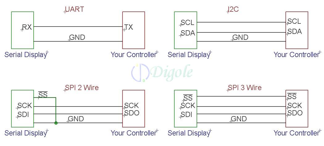
UART, I2C, SPI 2 wire, SPI 3 wire and lastly, 4 wire (full) SPI. An example of all four connections are shown below. In all of these cases, you need at least two things, a master device and a slave device. In our case, the master is our Arduino and the slave will be the MCP3008 ADC. Below also shows how you can daisy chain more slave devices to the same master bus. This is incredibly helpful because all of the devices are going to share up to three of the connections, and only have one connection that is unique to itself.


The shared connections are SCK, MOSI, and MISO while the unique connection is SS, but what do these connections mean?

MISO (Master In Slave Out) - The Slave line for sending data to the master,
MOSI (Master Out Slave In) - The Master line for sending data to the peripherals,
SCK (Serial Clock) - The clock pulses which synchronize data transmission generated by the master and one line specific for every device:
SS (Slave Select) - the pin on each device that the master can use to enable and disable specific devices.

Pretty simple, taken straight from the Arduino reference guide. You're probably wondering where the pins are. Now, you can write your own functions if you wanted to drop the external SPI slave anywhere, but a custom code is going to be much slower and it would be more easy to move your other connections somewhere else so that these pins are free for SPI:


Digital pin 13 is the Serial clock, 12 is Master Input, 11 is Master output and lastly, SS or Chip enable is 10, but I believe this can be moved where ever since it just requires a digitalWrite high or low. Low to enable of course.

That is about as complicated as it gets, honestly. Now, back to my needs. To iterate, I need to read the analog values of many potentiometers to assign to other devices, not on the SPI bus. We can do this two ways. Wire up all four connections, or wire up three connections and tie SS to ground on the slave only. If we keep SS connected to the Arduino, then we can expand the SPI bus to have more devices, more analog inputs, sensors, outputs, etc. IF we tie SS to ground, then the slave will always be active but can be the only SPI device on our bus.

Looking at the datasheet, there are two package types, the 3004 and the 3008. Both will take up all of the same connections, so lets focus on the 3008.


Pins 1 - 8 are the Analog input pins where we will connect the wiper of our pots. Pin 10 is the 1CS pin, which we will connect to !SS on the arduino. Pin 11 is the Din or Data input pin which will be connected to the Dout pin of the Arduino, MOSI. Pin 12 is the Dout which will be connected to the MISO pin. and lastly, the clock pin on 13 will be connected to Digital pin 13 on the Arduino.

Pins 16 and 15 will be bridged and connected to VCC or +5v. VDD is the supply and Vref is the reference voltage that the analog inputs are referencing. If we had a lower vref like 3v3, then our pots would have to be connected between Ground and 3v3, while the IC runs on +5v.

Pins 14 and 9 are the two grounds, Analog ground and digital ground, respectively. This may be one of the more confusing parts to hook up if you over think it. Copied stright from the datasheet:

"Utilizing the Digital and Analog Ground Pins The MCP3004/3008 devices provide both digital and analog ground connections to provide additional means of noise reduction. As is shown in Figure 6-5, the analog and digital circuitry is separated internal to the device. This reduces noise from the digital portion of the device being coupled into the analog portion of the device. The two grounds are connected internally through the substrate which has a resistance of 5 -10Ω. If no ground plane is utilized, both grounds must be connected to VSS on the board. If a ground plane is available, both digital and analog ground pins should be connected to the analog ground plane. If both an analog and a digital ground plane are available, both the digital and the analog ground pins should be connected to the analog ground plane. Following these steps will reduce the amount of digital noise from the rest of the board being coupled into the A/D converter."


What this basically means is that having analog ground and digital ground connected together may cause interference in the form of noise on the data traces. Since most of our Arduino board have only a single GND pin, we will have to take separating the two into our own hands. Some suggest dividing the two ground planes by a gap and then connecting them together via a small bridge like so:


They also suggest that you use separate power supplies. You should also remember to route any traces crossing the ground planes trough the bridge and not over the gaps. Being so strict will help you to reduce noise, but how much noise do you think that you actually have in your circuit? Are you running it on an unregulated series of AA batteries? A potato (joke)? Could you not afford filter capacitors? In most cases, the on board Arduino regulator is going to do its job in regulating the power supply, reducing noise and with capacitors between VCC and GND, yet more noise reduction.

Unless you plan on wiring up many different crystal oscillators, high speed devices, and wireless communications all on the same board, then your noise should not be readily noticeable.

Now enough of my tangents. I made up a quick MSpaint drawing of the connections:


That is the wiring diagram we will use, but for the time being, the MCP3008's are still in the mail. Once they arrive, I will write part 2 where we actually wire up the circuit and write some code to read from each pot. You may notice that the pinout is exactly 13 -> 13, 12 -> 12, 11 -> 11 and 10 -> 10. It would seem that the SPI functions were written to accommodate common SPI pinouts. You may see this on other SPI devices as well.

Thanks for reading!
Part 2: http://jazz-disassemblies.blogspot.com/2014/04/adding-analog-pins-to-arduino-pt2.html

Thursday, January 16, 2014

Jazz Disassemblies Ep4: N64 Gameboy Adapter Teardown

Some time ago, I needed the shell and cartridge connector of the gameboy adapter for the Nintendo 64, but I never throw things away. In light of this, I decided to de solder all of the components and write up a pinout diagram of the internal CPU itself.

This CPU is an 80-pin SMT IC just like the Original Gameboy, gameboy pocket and super gameboy however I am sure that it is more similar to the gamboy Color's CPU because of the abilities.

During my time desoldering everything, I forgot to record what components were so I no longer have that information. I would not have known some of the tiny transistor-like components anyhow because they had no markings.

In any case, I just want to share some photos with close ups of the traces and also the pin diagram.
Check it out:


I feel like I cheated on this dissassembly, because I have so little information. Sorry about that, I will just have to make the next one twice as in depth.

Thursday, November 14, 2013

Jazz-Assembly #2 - Yup, Another ArduinoBoy

Everyone and their mother has made one, so what took me so long? I have built them before, but this time I designed a PCB. What differs between mine and anyone else's is that I used economical parts rather than a pre built Arduino or an Atmega pulled form one with a bootloader.


Image Hosted by ImageShack.us

The entire board is a tiny 5cm x 5cm, MIDI connectors and LEDs included. I also plan on designing an acrylic shell to sell along side them, though anyone may choose to house it in their own enclosure.

Anyhow, this was the first time I had used SMT components besides an IC. Passive components including the resistors and caps were a new item for me to tackle. They did not challenge me as I had hoped. At one point, I blew one away from the pads, but it was all too easy to fix.

Image Hosted by ImageShack.us

Image Hosted by ImageShack.us

Image Hosted by ImageShack.us

Below is a shot for size comparison. You may have noticed in one of the photos that there is a notch on one side with a hole about 2 millimeters from it. This will be used for a zip tie so that I can ensure the cable does not break free. I will upload another picture once I complete that portion.

Image Hosted by ImageShack.us

Below is the wiring that I used to program both the flash and fuse bits. It is the same Bit Bang connection as we used on my version of the Gameboy Programmer board in a previous post. I found that the fuse bits were the most difficult to figure out in the whole project. in the end, I decided just to copy the fuse bits from a Pro Mini 5v/16MHz because that is what configuration I went with here.

Image Hosted by ImageShack.us

Thanks for reading. All credits for the ArduinoBoy go to Trash80 (Timothy Lamb) as can be found here:
https://code.google.com/p/arduinoboy/

Monday, October 28, 2013

Jazz Disassemblies Ep3: Sega Genesis Saving Teardown

I love the Sega Genesis, but rarely do anything with it. I have made a handful of reproduction carts in the past because there is nothing better than playing games on real hardware but I always have a regret after destroying a donor cartridge, whether it is sports or not. One of the goals I always set myself up with during a creating is to use 100% renewable components. By renewable, I mean of course modern and commercially produced components; nothing salvaged and nothing obsolete. Having nothing obsolete is very difficult in my circle of interests, but salvaging components is my greatest downfall.

During my journeys into the technologies that Sega and other companies used within the cartridges for the Sega Genesis/MegaDrive, I have found three official forms of saving data. Two forms use serial EEPROMs and the third uses the tried-and-true parallel SRAM with battery backup. My goal is to recreate these cartridges using new components and my stretch goal is to expand the addressable memory or just to improve them in some way while making the carts themselves renewable.

We already know that the plastic shells can be remade by the everyday hobbyist and their 3D printers and circuit boards can be fabricated by Chinese companies for pennies on the dollar. All that leave now is the components which are definitely on their way out of style. The components that we are looking for are 8- and 16-bit, parallel ROMs and RAMs. Referring to a statement above: by renewable I meant purchasable from Mouser or Digikey, etc in large quantities which will later be restored. Glancing at Mouser (My supplier of choice) I have already been able to locate a handful of ROMs and RAMs that come in both selectable 8- and 16-bit configurations!

The next goal I will have is to recreate the higher density logic with PLDs, but that is best left for another time.

1. KM62256 Parallel SRAM

These boards found in most of the miserable football and soccer games. Until I find another varient, I will cover one such board revision: "171-6279A"

The board seems to be made by Sega though I have long lost the ROM which was originally soldered in. It contains:

1x (CE) 47uF electrolytic capacitor
5x (C1-C5) .1uF ceramic capacitors
1x (BAT) CR2032 coin-cell battery
1x (IC1) 42-pin Mask ROM (27c160 equivalent) - 16Mbit
1x (IC2) KM62256BPL-7L, 32Kx8 bit (32Kbyte) Low Power CMOS Static RAM
1x (IC3) BA6162, Reset IC with battery backup function by Rohm
2x (IC4, IC5) 74HC00AP, Quad two-input NAND gate

I have already recreated everything on the board in Eagle PCB libraries including the board dimensions and general component layout. Tracing all of the connections is slower work and I will get to that eventually. In the meantime, my goal is to layout a functionally-identical board with 3v3 ROM/RAM, SMT caps and level shifters for proper data flow. THen we will have ourselves a flash cartridge!


Above you have seen the board itself with and without components. Ignore the text on the Mask ROM though since I just stuck a random IC in there to show it with one.

Looks pretty good if I do say so myself, though the traces are not as authentic as the layout. Sega never seemed to use top-side pads. They have vias which allow for double sided boards, but I have only seen EA cartridges that use top-side pads. These pads of course make for miserable desoldering since I need much more heat... and patience.

Some fun facts about this board is that the ROM is 16-bits but the SRAM is only 8-bit. Although I do not have the full details on how the software accesses these, the Gen/MD has two pins which are called !LDSW and !UDSW (Upper Data Set Write and Lower Data Set Write). When reading from RAM, the processor ignores the upper byte of data since there should be nothing there. While writing though, the !LDSW pin goes low which enables the !WE pin on our RAM. These two pins are for transferring 8-bits (one byte) at a time rather than 16 (two bytes).Not knowing how to activate either of these pins, it would seem that someone may add a second SRAM and use the currently unused !UDSW pin as the enable.


The above picture is how I found the glue logic for addressing our memories. Only 6 out of 8 gates are used which is a waste of space and battery power since the unused pins are connected to the Vout pin on our reset IC. If you think about it, the three NAND gates that have both inputs connected act as NOT gates which is something we would take into consideration if we were to redesign this with single-gate SMT ICs or on a PLD.

one problem I have with this board is that A21 and A22 are simply left hanging. Just a guess, but using A20 as a ROm address and A21 in the logic would expand the addressable memory, but Sega chose not to for some reason.

2. Acclaim Serial 24LC02B RAM

The next board I will cover is the P/N 670120 REV 2 by Acclaim. The contents of our board are as follow:

1x (C1) 47uF electrolytic capacitor
4x (C2-C5) 0.1uF ceramic capacitors
2x (R1, R2) 4.7K Ohm resistors
1x (U1) Mask ROM (capacity not yet known)
1x (U2) 74ALS138N, 1-of-8 decoder/demultiplexer
1x (U3) 74ALS74AN, Dual D-type flip-flop with set and reset
1x (U4) 74ALS125AN, Quad TRI-STATE Buffer
1x (U5) 24LC02B, I2C™ Serial EEPROM (2K capacity)

As you can see, the naming routines is different than that of Sega and yet again, we could reduce the chip count to much less with a PLD. U2-U4 could easily be designed in a PLD to reduce space and cost. For the time being, I assume the resistors are pull-ups or pull-downs.


3. Acclaim Serial 24LC04B RAM w/ LZ95A53

You're probably thinking that I recycled this board from a previous post and yes, yes I have. It does pertain to the topic though and I can probably shed a little more light on the special IC now that I know more about !LDSW and serial eeproms.

Anyhow, this board contains:

1x (C1) 47uF electrolytic capacitor
4x (C2-C5) 0.1uF ceramic capacitors
1x (R1) 10K Ohm resistor
2x (U1, U2) Mask ROMs (27c160 equivalents)
1x (U3) Acclaim LZ95A53 (memory mapper, glue logic, serial data interpreter, etc)
1x (U4) 24LC04B, I2C™ Serial EEPROM (4K capacity)


Above is the board that I created by probing all of the traces. Looks nice, but my next goal would be to reverse engineer the Acclaim's LZ95A53. Unfortunately, I have no scope to do so...


The above picture is my schematic which shows the connections on the LZ95A53. I had to make an addition to my cartridge connector since it uses several different pins that very few others use. I believe that the Acclaim's LZ95A53 IC contains the same logic as the board which used the 24lc02 serial RAM. Again, I cannot test this theory.


In hindsight, all of these boards used 27c160 equivalent Mask ROMs. The 27c160 can store a 2MB ROM which means the board with 2 Mask ROMs had a 4MB game. A piece of information for those making reproduction carts with the 27c400, 800, 160 and 322's, the first three mentioned all have a !BYTE pin. This pin allows for the EPROM to function as either an 8-bit or 16-bit ROM which means you may use it in many different systems.

Besides a little bit of work on the silkscreens, these boards are all ready to send to any fab house, granted they make 1.6mm thick boards. I will also be adding some more pictures of the other two boards shortly. Thanks for reading.

Friday, October 11, 2013

Gameboy MBC - Which to choose?

Just a quick overview for unfamiliar readers before we get into the thick of it.

The Nintendo Gameboy uses a Memory Bank Controller inside of official cartridges for switching between banks of memory and ultimately expanding the addressable memory. The MBC will switch between banks of both ROM and RAM so that the programmer may code larger games and backup more data in save files.

There are four main MBC's numbered 1 through 5 and excluding 4. The reason I am writing this is because each following revision did not simply add more addressable memory. Each one has unique capabilities built in as well as expanding the addressable memory. in general the MBC's function by waiting for specific data bits to be written to yet more specific memory locations. Once the data in question is written to the specific memory location, the MBC switches the active bank of ROM and RAM to accommodate more code.
I will summarize each MBC as well as quote some information from datasheets.

MBC1


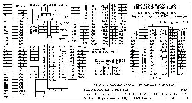
Is the first in the series of controllers which did only expand the addressable memory. Since the gameboy has 16 address pins and 8 data pins running through to the cartridge, the gameboy may without an MBC address only read from and write to a maximum of 256Kbits or 32Kbytes which is incredibly small considering Mario Land has 12 massive levels with multiple means of gameplay including the platformer and shooter, in both an airplane and submarine. Some of these levels even have secondary underworlds where Mario drops to an extra map off screen to collect secret coins or other items.

In any case, the MBC1 has two different modes to choose from. There is the 16Mbit ROM/8KByte RAM and 4Mbit ROM/32KByte RAM. 

Note: RAM is an external IC which needs to be connected to a battery while disconnected from gameboy power to retain data.

MBC2

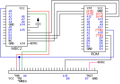
Similarly to the MBC1, the MBC2 maps extra banks of memory with specific memory writes; however, it may only map up to 2Mbits or 256Kbytes of ROM. Why a decrease? Well the magical thing about the MBC2 is that it contains 512 x 4 bits of SRAM built into the IC itself. This saves a lot of room on your cartridge board granted you are designing one.

The MBC2 can save money on RAM and space on your board if you are programming a small game that requires little ROM and RAM. Referring to the MBC1 above, if you wanted to offer a saving feature, you would need to source a RAM IC as well and route all of the Address, data and control pins to another location on the board.

MBC3

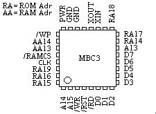
The MBC3 may again address up to 16Mbits of memory, but has a major feature built like the MBC2 has RAM. The MBC3 has an RTC or Real Time Clock built in. The RTC while still needing battery power when disconnected, offers a real-time count so that games such as pokemon may tell whether it is night or day, or when an hour in real life has passed for example.

Some games use the MBC3 without utilizing the RTC, but games that do include Pokemon of Generation 2 and Harvest Moon.

MBC5

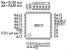
Lastly, the MBC5 is the final Memory Bank Controller from Nintendo. This particular MBC does not come with internal RAM or an RTC. It simply maps huge amounts of memory. It may map up to 64Mbits of ROM and up to 1Mbit of RAM but not both. There are different configurations to choose from; these are just the maximums.

This MBC which I find in nearly every Gameboy Color cartridge regardless of ROM size is guaranteed to work with the GBC's double speed mode. The others seem to work just fine too though, considering any GB game will run on your GBC.

For more information on how to use the MBC's with software, please refer to "Cartridge Types" in this document:
http://www.devrs.com/gb/files/gbspec.txt

MBC CPLD Clones & Reproductions

Aside from the Official Nintendo MBC's, people have had major success in recreating them using CPLD's. Both Homebrew developers and Chinese pirating companies that is.

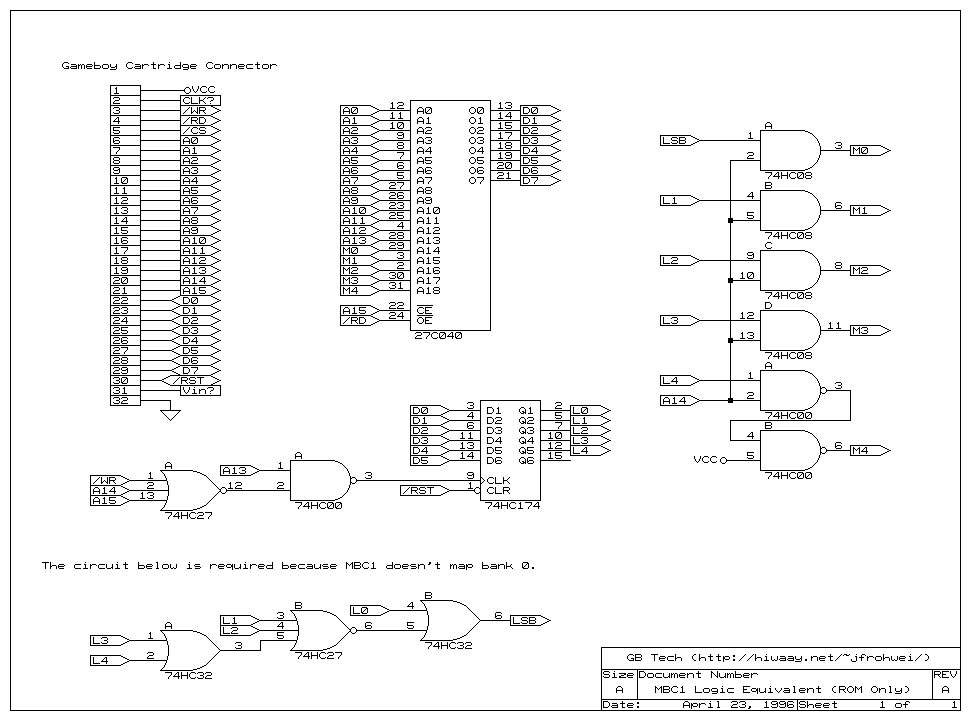
Since the MBC2 and MBC3 contain separate ICs, recreating them is much too difficult for a single person. MBC1 and MBC5 on the other hand can and have been redesigned by using CPLD's. They way they work as mentioned above is that they look for specific data bytes to be written to specific address locations. This Logic can be entirely drawn out using logic gates, which in turn can be programmed onto the CPLD.

MBC1 - CPLD

The MBC1 being the most simple, can be drawn using as little as 11 gates! (granted you do not need RAM)


MBC5 - CPLD

The MBC5 is much more complex of course, but it has also been cloned successfully by at least two separate people using two different CPLD's. One person used the XC9536 and the other person used the XC9572.

XC9536
http://chipmusic.org/forums/topic/2988/mbc5-clone-in-cpld/
and XC9572
http://home1.stofanet.dk/hvaba/gameboy/mbc5cpld/cpldcart.html

Depending on the number of inputs and outputs, more complex logic ought to be designed using PLD's or CPLD's. Not only can you save money on IC's, but space on your circuit boards. More often than not, a logic IC will take up space on your board and have a handful of unused pins and gates which is wasteful and lazy.

As always, thanks for reading! I hope I opened someone's eyes to new and old hardware.
Cheers